Combustion research
Combustion products and emissions
1. Measurement of NO x and soot emissions from the combustion plant
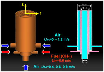
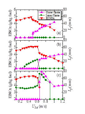
Due to the regulations of pollutants, we need to reduce emissions of nitrogen oxides (NOx) and soot particles in combustion. It is well known that NOx are pollutants to produce acid rain and photochemical smog. On the other hand, soot particles can penetrate into lung tissue and lead to serious pulmonary edema and cancer. In the present study, we focused on a triple port burner. The burner configuration is quite similar to a coannular burner for inverse diffusion flames. The burner has three concentric tubes, where air flows in both inner (central) and outer tubes and fuel flows in the annulus between air tubes (see Fig. 1). Since there are two boundaries between fuel and air, two nonpremixed flames are formed. NOx emissions (EINOx) were examined, which is shown in Fig. 2. It is found that the NOx emission index is decreased only when the outer flame is lifted. The maximum soot concentration and NOx emission are decreased when the flame is lifted, which could be explained with the partially premixing effect. To study further, the numerical simulation was also conducted.
Reference:
- K. Yamamoto, S. Kato, Y. Isobe, N. Hayashi, H. Yamashita, Lifted Flame? Structure of Coannular Jet Flames in a Triple Port Burner, Proceedings of the Combustion Institute, Volume 33, The Combustion Institute, pp.1195-1201, 2011.
2. Combustion characteristics of carbon particles
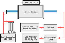
Continuous Regenerating Trap (CRT) is needed for future diesel exhaust after-treatment system. However, it is difficult to observe soot oxidation process. In this study, we used carbon particles as model soot, and measured carbon particle size and its number concentration to investigate the oxidation process in DPF, so that we could experimentally verify effects of NO2 on carbon particle oxidation (see Fig. 1). We used a tubular furnace where the temperature was controlled to evaluate the oxidation of carbon particles. The carbon particle size was monitored by SMPS (Scanning Mobility Particle Sizer). Then, the temperature and the degree of carbon oxidation were evaluated. As seen in Fig. 2, the mean diameter with NO2?is smaller, corresponding to the promotion of carbon oxidation by NO2. For comparison, measurement of CO and CO2 concentration was also conduced.
Reference:
- Y. Kanamori, K. Yamamoto, N. Hayashi, H. Yamashita, Experimental Study on Soot Particle Oxidation with NO2, 21th Internal Combustion Engine Symposium, pp.213-218, 2010.
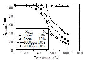
XNO2= 0 ~ 2000 ppm.
3. Simulation of continuous regeneration type DPF by Lattice Boltzmann method
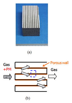
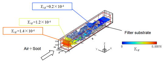
To reduce particulate matter (PM), including soot in diesel exhaust gas, a diesel particulate filter (DPF) has been developed. Since it is difficult to observe the phenomena in DPF experimentally, we have conducted a lattice Boltzmann simulation. In this study, we simulated the flow in a metallic filter. An X-ray computed tomography (CT) technique was applied to obtain its inner structure. Figure 1 shows photograph of cordierite DPF and PM trap inside porous filter wall. Calculation domain is shown by dotted line. The processes of soot deposition and oxidation were included for a continuously regenerating diesel filter. The amount of oxidized soot is increased with the filter temperature. When the filter temperature was higher, soot in exhaust gas could be almost completely eliminated in a continuously regenerating DPF. When the oxygen volume concentration is higher than 10%, which is the typical value in diesel exhaust gas, the soot is oxidized more significantly, and consequently, the after-treatment process in a continuously regenerating DPF is promoted.
Reference:
- K. Yamamoto, S. Oohori, H. Yamashita, S. Daido, Simulation on Soot??Deposition and Combustion in Diesel Particulate Filter, Proceedings of the Combustion Institute, Volume 32, The Combustion Institute, pp.1965-1972, 2009.
Turbulent combustion and modeling
1. Local structure and turbulent combustion rate of turbulent flame by laser diagnostic method
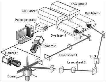
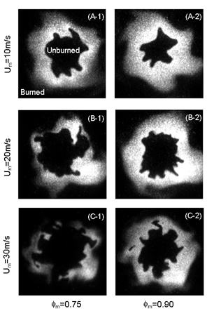
We have examined local flame structure by joint PLIF imaging, using simultaneous OH/HCHO-PLIF and orthogonal OH-PLIF measurements (see Fig. 1). We have used a cyclone-jet combustor to establish turbulent premixed flames for propane/air mixtures in a wide range of turbulence, covering the flamelet regime and thin reaction zones regime on combustion diagram. Figure 2 shows OH images in horizontal plane at different conditions. The sliced flame structures are well observed. As the mean exit velocity is increased, more wrinkling of the flame front is observed. Interestingly, at the lower equivalence ratio, the flame front could be distorted due to the turbulence. From the vertical and horizontal flame images, it is confirmed that this disconnected flame region is not the pocket of isolated unburned gas or surrounding air but the local flame extinction. The peak OH concentration in reaction zone becomes almost zero whereas HCHO concentration in preheat zone still remains. As a result, the large reduction of heat release rate occurs, resulting in local extinction. The turbulent burning velocity determined by the mean flame shape is increased with turbulence, and the bending effect is observed in thin reaction zones regime. On the other hand, different from the flame perimeter, the flame surface area is linearly increased. Since the turbulent burning velocity is well predicted by the classical formula in wrinkled flames, the bending is explained by the reduction of local burning velocity. Thus, within the frame work in our measurement, the flamelet approach could be still valid even in the thin reaction zones regime.
Reference:
- K. Yamamoto, S. Inoue, H. Yamashita, D. Shimokuri, S. Ishizuka, and Y.??? Onuma, PIV Measurement and Turbulence Scale in Turbulent Combustion, Heat? Transfer Asian Research, Vol.35, Issue 7, pp.501-512, 2006.
2. Study on the flame structure flow field of the floating flame
Usually, the diffusion flame is formed close to the burner rim by which the nozzles of fuel and air are separated, but at some conditions, the flame is lifted from these nozzles. In this case, the fuel and the oxidizer are partially mixed toward the leading-edge of the lifted flame. Recently, a direct numerical simulation (DNS) of lifted flames in turbulent flow has been conducted. It has been reported that, around the leading
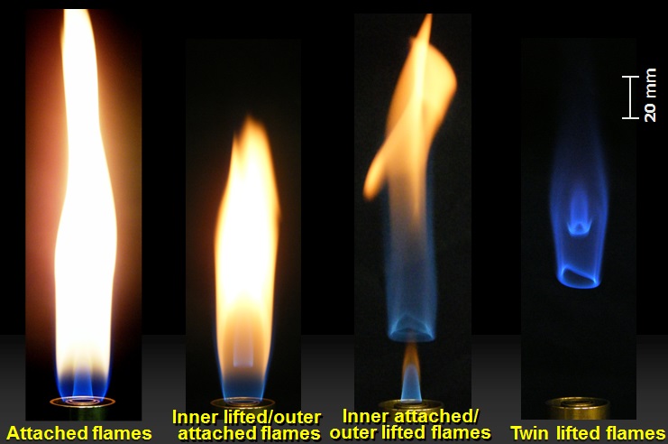
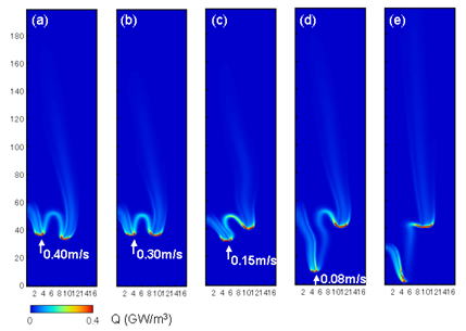
-edge flame, the incoming flow almost balances with the laminar burning velocity. Since a large number of flamelets exist in turbulent combustion, the interaction between the flame and flow is very complex. We are focusing on the interaction between two jet flames. So far, by using a triple port burner, the flame structure and flame characteristics including liftoff height have been examined. The burner has three concentric tubes, where air flows in both inner (central) and outer tubes and fuel flows in the annulus between air tubes. Since there are two boundaries between the fuel and the air in the triple port burner, two (inner and outer) flames are formed. Figure 1 shows photographs of the flames. In the triple port burner, depending on the flow conditions, four different flame configurations are observed; namely, attached flames in which the inner and outer flames are attached to the burner nozzle (Fig. 1a), inner lifted/outer attached flames in which only the inner flame is lifted (Fig. 1b), inner attached/outer lifted flames in which only the outer flame is lifted (Fig. 1c), and twin lifted flames in which both inner and outer flames are lifted (Fig. 1d). We focused on the inflow velocity near the flame edge at the location where the temperature is not yet increased. These values and evaluated locations shown by arrows are presented in Fig. 2. It is seen that the lifted flame behavior is determined by the conditions of inflow velocity toward the base of the lifted flame, which surely alters the transports of fuel and oxygen.
Reference:
- K. Yamamoto, S. Kato, Y. Isobe, N. Hayashi, H. Yamashita, Lifted Flame? Structure of Coannular Jet Flames in a Triple Port Burner, Proceedings of the Combustion Institute, Volume 33, The Combustion Institute, pp.1195-1201, 2011.
3. Experimental study on flame-wall interference
In recent years, the minimization of microelectronic devices and micro mechanical devices demands smaller and higher power generators. One of the candidates of such generator is ultra-micro gas turbine (UMGT), which is expected to have the several times higher energy density than lithium ion battery. For further developments of small scale combustors, it is important to understand their fundamental phenomena.
One of the important features of micro scale combustor is the large surface-to-volume ratio. The large ratio leads to enhance heat-loss and surface reaction on wall. However, they are very complex because of the effects of many factors such as temperature, materials, surface texture and so on.
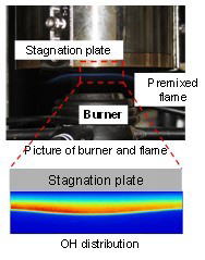
In this study, using stagnation-flow burner (Fig. 1), and changing the wall temperature and materials, we investigate about the influence of heat-loss on the stagnation wall temperature and the surface reaction.
4. Effect of droplet size and number density on flame propagation characteristics during spray combustion
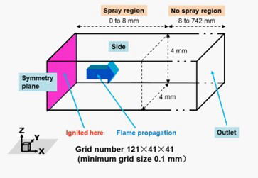
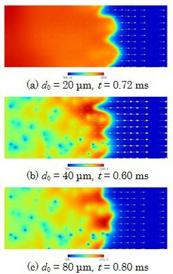
Spray combustion is a combustion mode which has been broadly utilized in direct injection internal combustion engine, gas turbine and so on. During spray combustion, many complex chemical and physical processes occur on each fuel droplet simultaneously, including fuel droplets preheated, evaporation, mixing, ignition, combustion and extinction. Due to spatial heterogeneous and time nonstationary process, spray combustion is very difficult to be clarified. Although characteristics of fuel droplets spray combustion have been researched numerically and experimentally, flame propagation characteristics in fuel spray have not been well explained. In this study, due to its complex process, we applied Crowe’s PSI-CELL model in order to simulate production of fuel gas, heating and evaporation of droplets. We ignite forcedly in fuel spray region in which many fuel droplets are dispersed randomly in air atmosphere. We examine the influence of droplet size and number density on flame propagation characteristic in fuel spray by numerical simulation. Especially, we elucidate the dominant parameter for flame propagation velocity. The following results are obtained. (1) The flame propagation velocities in fuel spray are almost bigger than the premixed mixture without droplets, because the flame becomes wrinkled due to the droplets. (2) In the condition of constant diameter of droplets, as the number density is increasing, the flame propagation velocity increases firstly, and then decreases. (3) In spray combustion, as equivalence ratio increases, flame propagates rapidly at first, then becomes extinction in propagation process.
From:
J. Li, H. Yamashita, Proceedings of the 49th Combustion Symposium, (2011), pp.292-293
Flame properties and risk analysis
1. Flame structure and spreading speed that spreads on flammable solids
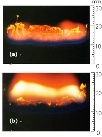
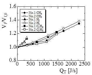
We have investigated the downward flame spread over a thin solid fuel. Hydrogen, methane, or propane, included in the gaseous product of pyrolysis reaction, is added in the ambient air. The fuel concentration is kept below the lean flammability limit to observe the partially premixing effect. Both experimental and numerical studies have been conducted. Results show that, in partially premixed atmospheres, both blue flame and luminous flame regions are enlarged, which is shown in Fig. 1. Simultaneously, the flame spread rate is increased. Based on the flame index, a so-called triple flame is observed. The heat release rate ahead of the original diffusion flame is increased by adding the fuel, and its profile is moved upstream. Here, we focus on the heat input by adding the fuel in the opposed air, which could be a direct factor to intensify the combustion reaction. As seen in Fig. 2, the dependence of the flame spread rate on the heat input is almost the same for methane and propane/air mixtures, but larger effect is observed for hydrogen/air mixture. Since the deficient reactant in lean mixture is fuel, the larger effect of hydrogen could be explained based on the Lewis number consideration. That is, the combustion is surely intensified for all cases, but this effect is larger for lean hydrogen/air mixture (Le < 1), because more fuel diffuses toward the lean premixed flame ahead of the original diffusion flame. Resultantly, the pyrolysis reaction is promoted to support the higher flame spread rate.
Reference:
- K. Yamamoto, Y. Ogata, H. Yamashita, Flame Structure and Flame Spread Rate over a Solid Fuel in Partially Premixed Atmospheres, Proceedings of the Combustion Institute, Volume 33, The Combustion Institute, pp.2441-2448, 2011.
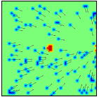
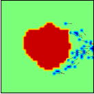
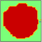
2. Evacuation simulation in case of fire by real number cellular automaton method
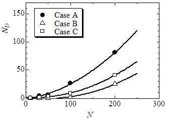
We present simulation of fire evacuation by real-coded Cellular Automata (RCA), which is a new approach for pedestrian dynamics. We consider three cases where only the number and location of the exit are different. There is one exit in case A. There are two exits in case B, which are located at both sides. In case C, there are two exits, but these are located at the same side. Each room size is 16m×16m, and the exit width, W, is 1.2 or 2.4 m. To describe the flame spread in fire, a percolation model is applied, where the flame position is determined stochastically. In the simulation, we focus on several parameters including the number of people in room, the route keeping away from the flame, and the location of the exit. Figure 1 shows the dynamics of fire evacuation. The calculation domain is case A, and there are 100 people in the room. The exit width is 1.2 m, and the evacuee velocity is 2.2 m/s. The distance between the evacuee and the flame is set to be 1.6 m. Three results at t = 0.5, 5.0, and 9.0 s are shown. The evacuees who can move directly toward the exit are not affected by the burning area. However, those passing near the burning area must keep away from the flame and take the longer route. Next, we changed the number and location of the exit. In case A, the exit width is W= 2.4 m. On the other hand, we set W = 1.2 m in cases B and C, ensuring that the total exit width is 2.4 m. By changing number of people in room, we examine the number of fatalities involved in fire (ND) in three cases. Results are shown in Fig. 2. Expectedly, as more people in the room, the number of fatalities increases. In case A, even though the bottleneck is less observed at wider exit, the evacuee must take longer route. There are more chances to be involved in fire. In case C, although the situation is similar to case A, ND is smaller. By comparing three cases, ND in case B is the smallest. This is because the evacuee can move in the same direction of flame spread, and less chances to be involved in fire.
Reference:
- K. Yamamoto, S. Kokubo, K. Nishinari, Simulation for Pedestrian Dynamics? by Real-Coded Cellular Automata (RCA), Physica A 379, pp.654-660, 2007.